Project Overview
In this project we had to design a digital sixty second timer that counts from 0 to 59. There are two control inputs and two output displays. The two inputs are the clock and reset. The clock controls the count rate and the reset signal resets the count to zero. When the count gets to 59 it resets to 0.

PLD Circuit
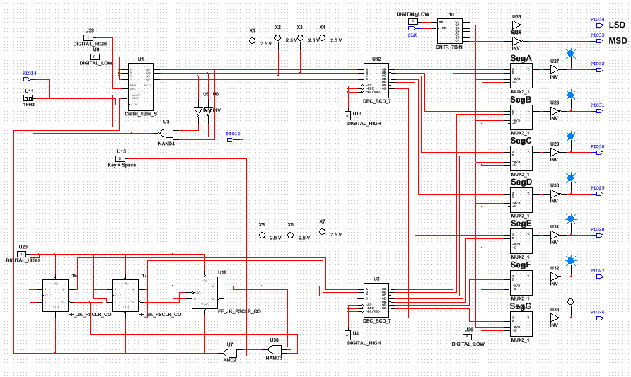
This project is very similar to the last project. The last project we had to create a digital counter that counts to 80 and when it gets to 80 it pauses. We also had to make a reset button to set the counter to zero. So they are similar because they both are counters and have reset buttons. They are different because of the materials they used to create each counter. This counter used j/k flip flops. The other project used 74ls74n counters.
Final Project Conclusions
1. Asynchronous counters is where only the first flip flop is clocked by an external clock. Al subscript flip flops are clocked by the output of the preceding flip flop. Synchronous counters are flip flops that are simultaneously clocked by the external clock. Synchronous counters are also faster, have no ripple effect, and require more logic.
2. The difference between the 163 and 193 is that the 193 is a 4 bit up and down counter and the 163 is a 4 bit up counter. Also the 163 has a sync load and a sync clear, the 193 has a async load and async clear. Also the 163 also will show the detected number.
3. We had to create a 60 second timer using j/k flip flops and a 4 bin counter. We had to get the display to show 59 and then go back to zero. Since the last project before was so similar i just used that project to help me. I used the pld from the last project and just switched the components needed to build the 60 second timer. We also needed less probes because we didn't need to get to such a high number. After we got the circuit working on the computer we had to build the 60 second timer on a breadboard using wires. The breadboard is supposed to display a counter from 0 to 59 and then back to zero. We have to use the circuit we made on the computer to create the breadboard circuit. You have to use the led numbers and the letter with the number from the circuit on the computer and match the same number that's on the chip given to us with the same letter using a wire. We repeat the step for every led light shown on the circuit on the computer screen. If everything works perfectly the digital counter on the board should count from 0 to 59 and then back to zero and just repeats over and over again until you pause or stop the simulation.
4. I think some other students started from scratch instead of just using the last project to build the circuit like i did. i think this method was a bit easier than starting over in my eyes.
