Project overview
The purpose of this project is be able to show our birthdays on a single seven segment display. A constraint we had was we could just use the last two digits of the year we were born to make it easier. This report will explain to demonstrate our unique birthdays on a circuit display.
Truth Table
The purpose of the truth table is to explain how the circuit would work. It tells us when x,y,z are on/off and what numbers the circuit should display. It also tells us when a,b,c,d,e,f,g are on/off and what numbers they will display.
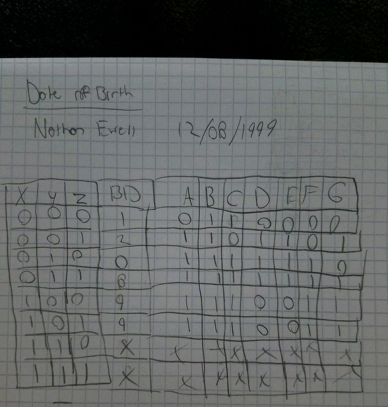
The a through g colums represent which part of the number will be on or off. Think about a number zero on a old fasion clock. There are 7 different lines to create the number 0, so if all the letters are on the display will so the number 0. The x just means dont worry about the last two colums because we were told not to use the first 2 digits in the year we were born. So basically they are represented as on or ones.
K-Maps and simplified logic for 7 segments
We used K mapping to create our expressions for each letter. So for example to find the expression for A you take the A column in the truth table and fill in a 2 by 4 table with 1s and 0s. You lable the table by having two variables on the left side and one variable on the top. For the left you lable both variables off, first one, both on, and then second on. The top you just lable on/off. The next step is grouping. You group the ones on the table however you can, either by 2's, 4's, or a method called pac maning. Then after your done grouping you create your expressions. To create your expressions you take a group and see which variables dont change Then you just add your groups together. Also if your table is full of ones then the expression is just one. The x's are represented as ones. We used the sum of products form so it was the most simplified version.We used k mapping instead of boolean algebra because k mapping is a lot easier and less chance for error. We have 7 expressions because we have 7 letters.
MultiSim implementation
This picture shows the circuit i built on multisim using a seven segment display to show my birthday. It shows the inverters, the bus, the different chips, and the number that is displaying.
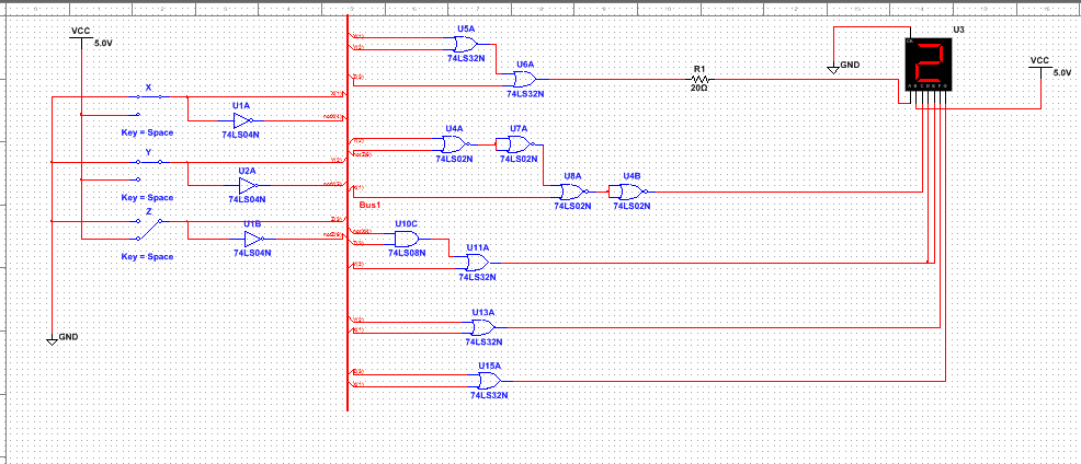
My circuit is in bus form because it makes it easier to read. If it wasnt in bus there would be so wires it would get confusing to read. I needed 5 or gates, 1 and gate, 3 inverters, and 4 NOR gates to complete my circuit. I would need 1 NOR chip, 1 And chip, 1 inverter chip, and 2 or chips.
I used NOR gates because most of my circuit was OR gates so it was easier. We use NAND and NOR gates to simplifly our circuits so we would use less chips wiring our cuircuit which would cut back on the cost making it more efficient. For my circuit is didnt simplify it, i actually added a gate. Also it didnt change the number of chips because it just needed one NOR chip for my circuit.
The seven segment works by having 7 different circuits connected to it.The difference between the two displays is the common cathode has all the cathodes of the 7-segments connected directly together and the common anode has all the anodes of the 7-segments connected together. I used the common cathode display because it shows the high output which would make it easier for us to make our expressions.The purpose of the resistors was just to make sure the segment wouldnt fry and that it didnt recieve too much voltage.
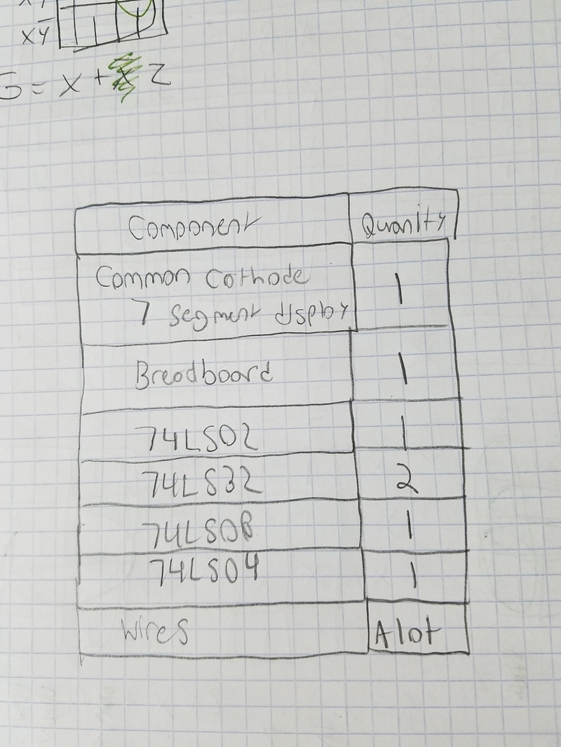
Bill of Materials
This bill of materials shows what all was needed to complete this date of birth project.
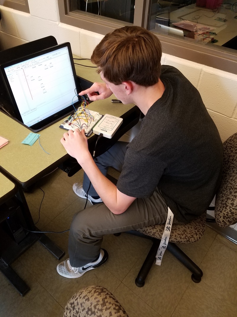
Bread-boarding
I believe this bread boarding experience was a huge success compared to the one before where i didnt finish. I learned a lot of things, like how to read the packet showing the chips and where to put the wires and where the output comes. It was a little difficult when you start having a lot of wires on your board because its hard to manuver through all the wires to get to a certain place. Luckily mine worked the first time, i could see how it would be a pain trying to figure what is wrong with your board because there is so many possilbilites.
Conclusion
I learned how to efficiently bread board and also how to better understand what we have been learning about k mapping and about multisim. The only thing i would do differently is manage my time better so i wasnt rushing to finish the last day of class time to work on the project. I dont really have any questions about the concepts addressed, this project helped me a lot in understanding them because the first project i was mostly confused on how to do things but now i think i got a good understanding. K mapping is useful because its a lot easier than boolean algebra and its less chance of error accuring.
