Project Overview
This project we had to create a circuit using flip flops to make two separate counters and make the ones counter trigger the tens counter. Then we had to make the counter pause at 80. We also had to make a reset switch to at any time set the counter to zero.
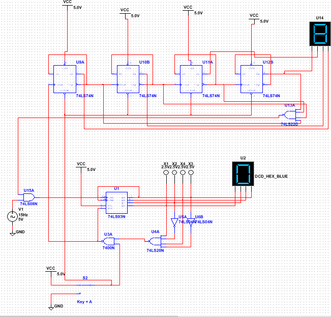
Multisim circuit
PLD circuit
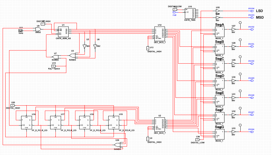
The PLD mode is different from the design mode because it is supposed to upload the circuit on circuit board. The PLD mode, there needs to be pins that send signals out to the gates and pins that will receive signals from the board. The components on PLD mode are not as specific as they need to be able to function on different types of boards. Also the circuit can be transferred to the board through the program.
Bill of Materials
Materials Quantity
NI myDAQ 1
Programmable Chip 1
Breadboard 1
Wires a lot
NI myDAQ 1
Programmable Chip 1
Breadboard 1
Wires a lot
Final project conclusions
1. The SSI is the small scale integration and it usually has less than 100 components and around 10 gates. The MSI circuit is the medium scale integration where it contains less than 500 components The ripple effect is where only the first flip flop is clocked by an external clock. AI subscript flip flops are clocked by the output of the preceding flip flop.
2. The limitations we had was that first we had to make two separate counters then we had to make the ones counter trigger the tens counter. Then we had to make both displays show 80 and also pause at 80.
3.The ripple effect is where only the first flip flop is clocked by an external clock. AI subscript flip flops are clocked by the output of the preceding flip flop.
4.Once power is sent through to the clock the 93 chip will count from 0 to 9 then at the 9 the NAND gate will trigger and send one signal through to the flip-flop clock and that signal will raise the tens display count by 1.
5. Everyone in the class had the same two counters but some people had different reset buttons.
